ESP-32 Cam + Arduino IDE = IOT Surveillance Car Arduino Projects For Beginners

The AI-Thinker ESP32-CAM module comes with an ESP32-S chip, a very small size OV2640 camera and a microSD card slot. MicroSD card slot can be used to store images taken from the camera. Here HTTP communication protocol will be used to receive video streaming from the OV2640 camera over the web browser. Components Required ESP32-CAM 4WD CAR Chasis FTDI Programmer DC Motors (4) Jumper Wires Wifi Antenna Motor Driver (L298N) Battery Installing ESP32 Board on Arduino IDE We will program the ESP32-CAM using Arduino IDE . For that, we have to install the ESP32 add-on on Arduino IDE. To install the ESP32 board in your Arduino IDE, go to File> Preferences Now copy the below link and paste it into the “Additional Board Manager URLs” field, as shown in the image below. Then, click the “OK” button: https://dl.espressif.com/dl/package_esp32_index.json Now go to Tools > Board > Board...


Well
ReplyDeleteThanks
ReplyDeleteKindly send the code
ReplyDeleteAwesome Dude Keep It Up
ReplyDeleteyour code can be shorter
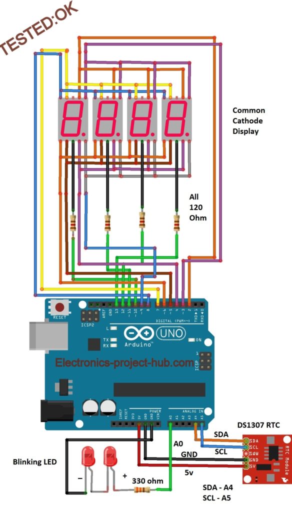
ReplyDeleteif (tm.Hour > 12)
{
tm.Hour = tm.Hour - 12;
}
else
{
if (tm.Hour == 0) Hour = 12;
}